Energetic Basis of Coiled Coil Topology and Oligomeric State Specificity"
[Ph.D. Thesis]
“Energetic Determinants of Oligomeric State Specificity in Coiled Coils”
[J. Am. Chem. Soc, (2006), 128(48); 15499-15510]
"Computational Analysis of Residue Contributions to Coiled-Coil Topology"
[Protein Science, (2011), 20:1845-55]
Coiled coils comprise two to five right-handed α-helices which wrap around each other in a slight left-handed superhelical twist. The typical sequence of a coiled coil is characterized by a heptad repeat commonly denoted by the letters abcdefg, where residues in positions a and d are predominantly hydrophobic, while those in positions b, c, e, f, and g are usually charged or polar. Coiled coils occur in nature as the dominant motif in fibrous proteins and as mediators of oligomerization. The oligomerization interface between supercoiled helices is made by knobs-into-holes meshing of side chains at the interface.
Empirical rules have been established on the tendency of different core sequences to form a certain oligomeric state and topology but the physical forces behind this specificity are unclear.
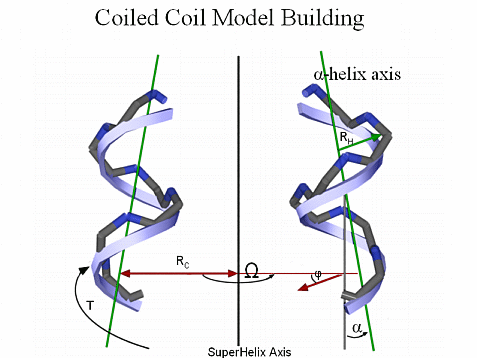
The geometry of the Coiled Coil Motif can be parameterized. We have built backbone coordinates for different topologies and oligomeric states using Crick’s mathematical model for an ideal coiled coil [Crick, F.H.C. Acta Crystallogr. 6, 685-689 (1953)].
For example, to build a dimer, we start by generating a straight, 3.5 residues/turn helix along the Z axis. The 3.5 residue/turn periodicity positions each a and d residue such that they line up along the helical axis rather than spiraling around the helix as in a canonical α-helix. The atomic coordinates Xi, Yi, and Zi, for the backbone atoms in the straight helix are given by,
                Xi = RH sin (θt + φ)
	Yi = RH cos (θt + φ)
	Zi = Zi-1 + dZ
Where the value of θ is 4π/21 radians, the parameter t runs over integral values generating three atoms per residue, and the values of RH and dZ depend on the atom type (N, Cα, C). The parameter φ is chosen to position the a and d residues toward the center of the coiled coil and is determined by the heptad assignment of the first residue in the sequence.
The initial helix is then translated along the X axis by a value equal to the coiled coil radius and given a left-handed twist using Crick’s Equations for an ideal coiled coil. The second helix is generated by translating the initial helix along the X axis by a value equal to the coiled coil radius, rotating it by 1800 about the coiled coil axis and giving it a left-handed twist creating the dimeric coiled coil. The atomic coordinates XC, YC, and ZC, of the coiled coil backbone atoms are given by,
     XC = [RC cos (T + Ω)] + [Xi cos (T + Ω)] + [Yi cos α sin (T + Ω)]
     YC = [-RC sin (T + Ω)] - [Xi sin (T + Ω)] + [Yi cos α cos (T + Ω)]
     ZC = Zi + Yi sin α
Where the angular and spatial separation of the component helices in the coiled coil are denoted by Ω and RC, respectively. The parameter α is the tilting angle of the component helices and is obtained by α = 2π RC / PC, where PC is the coiled coil pitch. The angular displacement of the initial helix in the coiled coil frame is given by T = 2π (ZH - Z0) / PC.
The angular separation Ω for a dimeric coil takes on values of 00 and 1800 for helix A and B respectively. For trimeric coils, Ω has values of 00, 1200 and 2400, while in tetrameric coils Ω has values of 00, 900, 1800, and 2700.

Jorge Ramos, Ph.D.
-|- SEMPER FI -|-
CURRENT DUTIES/HOBBIES

CONTACT INFORMATION
Department of Chemistry
Queens College of New York
65-30 Kissena Blvd.
Queens, NY 11367
tel: +1-718-997-3273
EMAIL:jr_starwind@netzero.net
